RF passband filters
Guide · updated July 2026
A band-pass filter lets your band through and throws everything else away. That sounds minor until a nearby transmitter deafens your receiver — then it’s the difference between hearing the mesh and hearing nothing. Here’s the deep version: why front ends overload, how cavity, SAW and ceramic filters really compare, where each one belongs, and why a 915 MHz node at a tower almost always needs one.
Why filter at all: front-end overload
Every receiver has a dynamic range — the gap between the faintest signal it can dig out and the strongest it can tolerate before its front end (the low-noise amplifier and mixer) stops behaving. Push past the top of that range and two ugly things happen, even when the offending signal is nowhere near your frequency:
- Blocking / desensitization. A strong off-channel signal drives the LNA or mixer into gain compression — the amplifier runs out of headroom and its gain for your weak signal collapses. Your receiver goes deaf. This is “desense,” and it needs nothing more than raw power arriving at the antenna.
- Intermodulation (IMD). Feed two strong signals into a front end that isn’t perfectly linear and they mix, producing sum-and-difference products. Some of those products land right inside your passband — phantom signals and a raised noise floor manufactured inside your own radio.
A receiver can’t tell the difference between a real weak signal and interference it created itself. The fix is to stop the out-of-band energy before it ever reaches the vulnerable stages. That’s the job of a band-pass filter (a “preselector”): mounted as close to the antenna as possible, ahead of any gain, it passes the sliver of spectrum you want and rejects everything else, so that energy never gets to consume dynamic range or brew up IMD.
The three kinds you’ll meet
They all pass a band and reject the rest — but they trade loss, sharpness, power handling, size and cost against each other in very different ways.
| Type | Insertion loss | Passband & selectivity | Power handling | Tunable? | Size & cost |
|---|---|---|---|---|---|
| Cavity | ~0.5–3 dB | Narrow, tunable; very high Q (~2,000–20,000), rejection 75–100 dB | High — watts to kW | Yes (screws + analyzer) | Large, heavy; ~$100–$1000+ |
| SAW | ~1.5–3.5 dB | Fixed; sharp for its size (e.g. 26 MHz @ 915) | Low — often ~+10 to +25 dBm | No (fixed at manufacture) | Tiny (~a few mm); cents–few $ |
| Ceramic | ~1.5–4 dB | Fixed; moderate Q (~500–1500), 1–30% wide | Moderate (> SAW) | No (factory-set) | Small; ~$1–10 |
The single most important spec here is the one people skip: power handling. It decides where in the radio a filter is allowed to live — and getting that wrong is how a good filter dies. More on that below.
Cavity filters
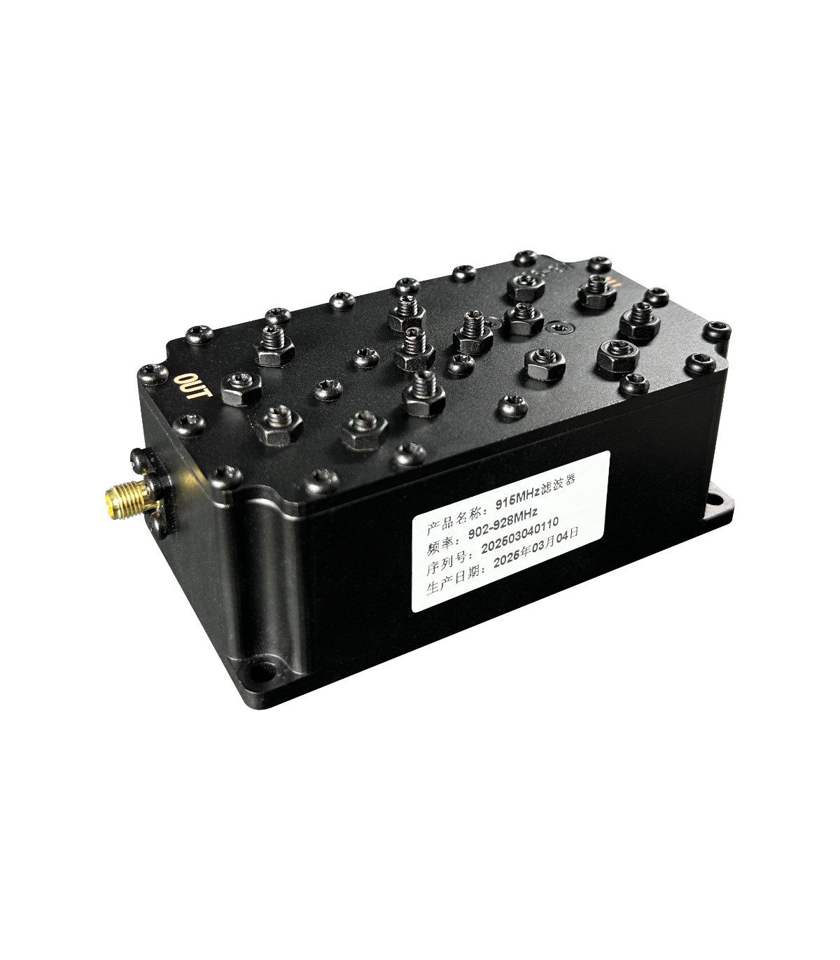
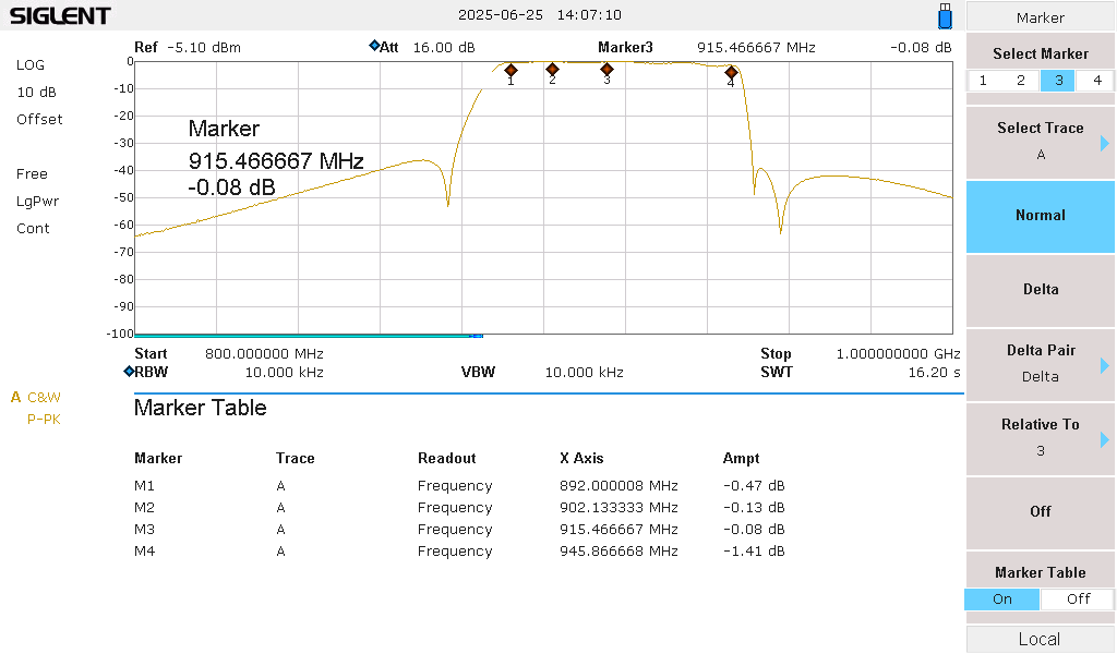
A cavity filter is a resonant metal can — a machined chamber with a tuned rod inside. That geometry gives it an enormous Q (a few thousand to tens of thousands), and high Q buys you the two things that matter most: very low insertion loss (well under a decibel for a large one, and around 2 to 3 dB for a compact, sharp 915 MHz unit) together with brutal selectivity — 75 to 100 dB of rejection, with skirts steep enough to kill a signal sitting just outside your band.
They also handle real power — watts to kilowatts — which is what lets a single cavity filter sit in the full transmit-and-receive path. The catch is everything else: they’re big and heavy (a 915 MHz outdoor cavity is a 3 kg aluminum brick), expensive (roughly $100 to $1000+; a name-brand 915 unit runs about $290), and they must be tuned. Tuning means turning the adjustment screws while you watch the response on a spectrum analyzer with a tracking generator, or a VNA — and because the metal expands and contracts, a cavity can drift with temperature.
- Good for: tower and co-location sites, high-power stations, anywhere you need deep rejection close to your own band.
- Bad for: weight- or budget-limited installs, and quiet sites where you simply don’t need it — you’d be paying insertion loss (and lugging 3 kg) for rejection nothing is asking for.
SAW filters
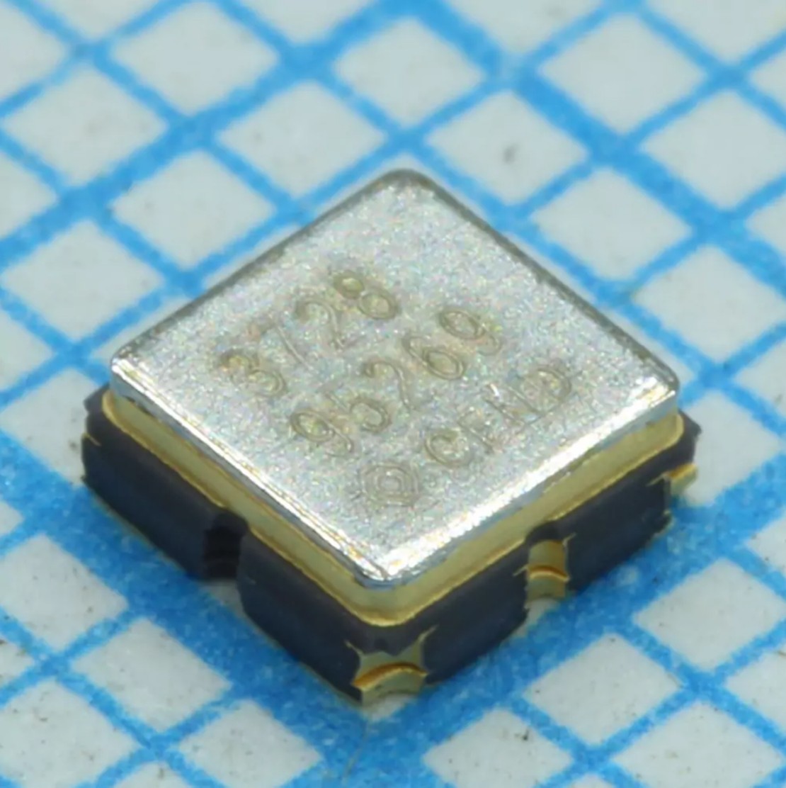
A surface acoustic wave filter turns your RF into a tiny mechanical wave rippling across a piezoelectric crystal and back into RF, using the geometry of metal fingers printed on the surface to define the passband. The result is a remarkable amount of selectivity in a chip just a few millimeters on a side that costs pennies — which is why there’s a SAW filter in the front end of nearly every phone, and in LoRa modules that include one. Insertion loss is moderate (roughly 1.5–3.5 dB; a common 915 MHz ISM part is about 2.2 dB over 902–928), and the frequency is fixed at manufacture — there is nothing to tune.
The trap is power. Those delicate metal fingers take far less RF than a cavity can — often just +10 to +25 dBm maximum, and the smallest, cheapest parts as little as +10 dBm. Push past the rating and the fingers erode or crack. Some 915 MHz ISM SAWs are rated high enough to sit in a modest transmit path, but plenty are receive-only — so the rule isn’t “never transmit through a SAW,” it’s never exceed its (small) power rating, which even a low-power radio can do.
- Good for: the receive front end of mass-produced radios — tiny, cheap, sharp, and effective at rejecting nearby services before the LNA.
- Bad for: anywhere the transmit power can exceed its small rating, and any job that needs a different frequency than the one it was born with.
You probably already have one. Most receivers already carry a built-in front-end filter — the preselector — and it’s usually a SAW (or ceramic) part sitting right behind the antenna. That’s exactly what a bare module like the RAK4631 leaves out (see below), which is why external filtering matters more for it — and it’s also why even a filtered receiver can still be swamped at a truly hostile site, where a factory SAW simply doesn’t have enough rejection to cope.
Ceramic filters
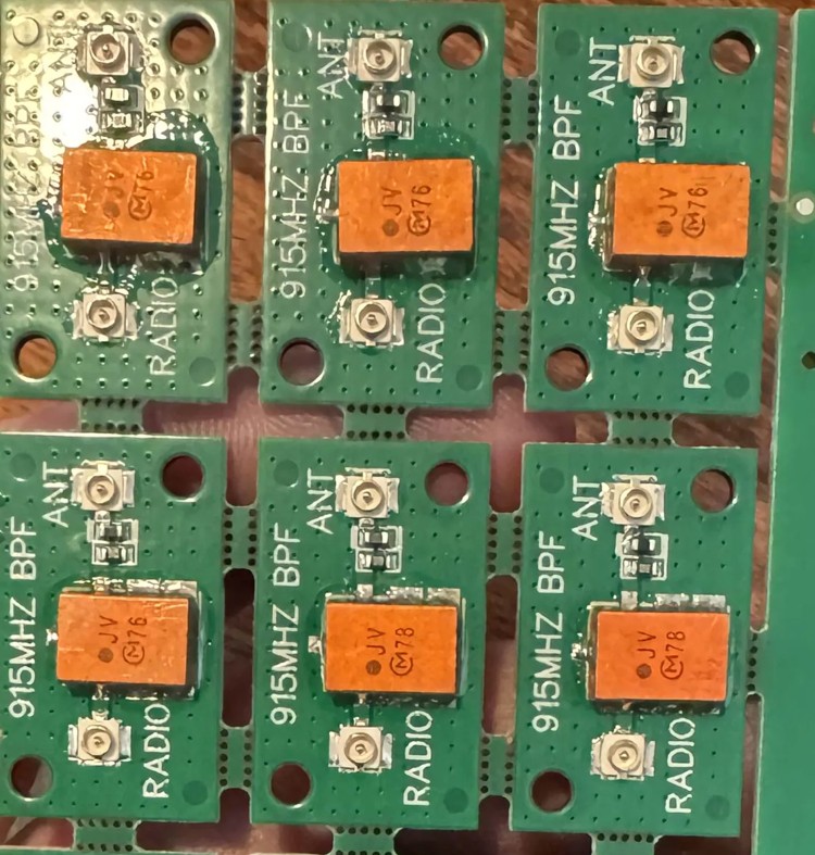
Ceramic filters use resonators made of a high-dielectric ceramic — coaxial resonators or a monolithic block. They land squarely in the middle: a Q of roughly 500–1500 (well short of a cavity), moderate insertion loss (~1.5–4 dB), and enough power handling to beat a SAW. They’re small, cheap ($1–10), stable, and factory-set — not something you tune in the field. Ceramic block duplexers are what let a phone or a base station share one antenna for transmit and receive. They’re a fine fixed filter when a SAW can’t take the heat and a cavity is overkill.
Where you put it matters — a lot
A node with one antenna switches it between transmit and receive with an RF (antenna) switch. That gives a filter two possible homes, and they are not interchangeable:
- At the common antenna port — between the antenna and the switch. Here the filter sees everything: your full transmit power on the way out, and every incoming signal on the way in. It cleans up your transmitted harmonics and protects the receiver — but it has to survive your transmitter. This is cavity-filter territory.
- In the receive-only path — between the switch and the receiver input. Here the filter only ever sees weak received signals, never transmit power. This is where a low-power SAW or ceramic front-end filter is safe, and where it does its job of rejecting out-of-band energy before the LNA.
The classic way to kill a filter. A RAK4631 (Semtech SX1262) has no built-in front-end filter and transmits at up to +22 dBm. Reach for a tidy little receive SAW like the Qualcomm/RF360 B39921B3728U410 — a lovely 915 MHz part, but its datasheet allows only +18 dBm on a 10%-duty burst, and just +15 dBm on a continuous carrier. A LoRa packet transmits continuously, so the RAK4631’s +22 dBm runs it 4 to 7 dB past its limit. Wire it into the common antenna port and the very first transmit overdrives it — it dies, often silently. A receive-only SAW belongs in the receive-only path; only a high-power filter (a cavity) belongs where transmit power flows. Match the filter’s power rating to its position, every time.
MeshCore 915: home vs the tower
The 902–928 MHz ISM band that US MeshCore and LoRa live in is surrounded by loud neighbors: cellular and SMR services below and around it, and — the real menace — one-way paging transmitters just above the band, around 929–932 MHz, often running hundreds of watts. A pager sitting 1 MHz above the edge of your band is exactly the kind of signal a bare front end can’t cope with.
So the answer to “do I need a filter?” is genuinely it depends on where you are:
- A quiet backyard node usually doesn’t. There’s nothing strong nearby to overload it, and a filter’s insertion loss would only shave a little sensitivity off your receive for no benefit. Don’t add filtering the environment isn’t asking for.
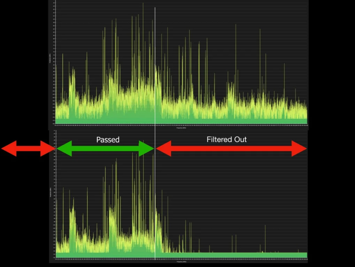
- A node at a commercial tower is a different world. You’re now feet away from paging, cellular and land-mobile transmitters putting out tens to hundreds of watts. Without a filter, that wall of energy desenses your receiver — the node may hear nothing despite a perfect antenna. A cavity band-pass filter at the antenna port passes 902–928 and slams the door on everything else; operators routinely report the receive noise floor dropping and signal-to-noise jumping by 10–20 dB the moment it goes inline. At a site like that, the filter isn’t an upgrade — it’s the thing that makes the node work at all.
That’s the whole reason cavity filters are treated as near-mandatory for tower installs: the interference environment leaves no other option, and only a cavity has both the rejection and the power handling to sit in the full path and take it.
Best practices
Filter for your environment, not for its own sake
Every filter costs insertion loss, which costs a little transmit power and receive sensitivity. At a quiet site, skip it. At a noisy one, it pays for itself many times over.
Match the power rating to the position
Common antenna port (transmit + receive) → a high-power filter, i.e. a cavity. Receive-only path → a low-power SAW or ceramic is fine. Never put a receive SAW where transmit power flows.
Put it near the front end
As close to the antenna as practical, ahead of any amplifier — a filter after the LNA can’t un-overload it.
Mind the insertion loss on receive
A filter ahead of the LNA adds directly to your noise figure. Use a low-loss filter, and keep the run to it short.
Tune and check with the right gear
Cavities need a spectrum analyzer (with tracking generator) or a VNA to tune, and can drift with temperature — re-check seasonally. SAW and ceramic are fixed; there’s nothing to adjust.
At a tower, plan for a cavity from day one
Co-location interference is the norm, not the exception. Budget the size, weight, cost and insertion loss into the install before you climb.
Go deeper
Fighting desense at your site?
Bring your spectrum shots and your setup to #antennas — we’ll help you figure out whether you need a filter, and which one.